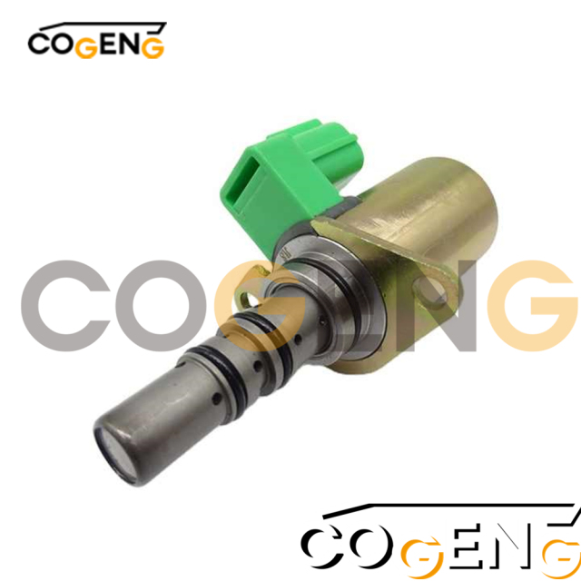
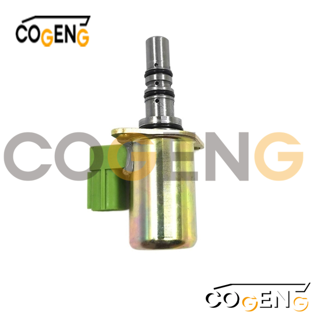
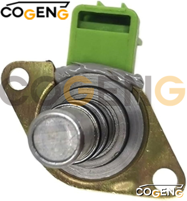
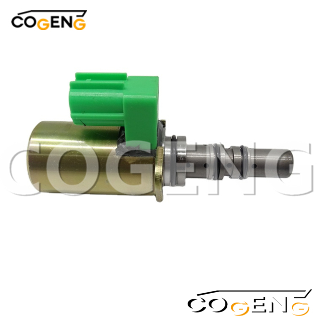
| COGENG Part Number | KVL-35F04 | KVL-35F05 | KVL-35F06 |
| Replaces OEM Part | YT35V00004F1 | YT35V00005F1 | YT35V00006F1 |
| Primary Function | Swing Brake Control | Travel Control | Implement Control |
| Identification Color | Blue Dot | Green Dot | Yellow Dot |
| Electrical Specifications | |||
| - Operating Voltage | 24V DC ±10% | 24V DC ±10% | 24V DC ±10% |
| - Current @ 20°C | 1.0A | 1.2A | 1.1A |
| - Response Time | < 15ms | < 22ms | < 18ms |
| - Resistance @ 20°C | 24Ω ±10% | 20Ω ±10% | 22Ω ±10% |
| Hydraulic Performance | |||
| - Max Operating Pressure | 350 bar | 350 bar | 350 bar |
| - Flow Rate @ 10 bar ΔP | 18 L/min | 25 L/min | 22 L/min |
| - Hysteresis | < 2.5% | < 2.5% | < 2.5% |
| - Leakage Rate | < 2 drops/min | < 2 drops/min | < 2 drops/min |
| Physical Specifications | |||
| - Housing Material | Nickel-Plated Brass | Nickel-Plated Brass | Nickel-Plated Brass |
| - Plunger Coating | Diamond-Like Carbon | Diamond-Like Carbon | Diamond-Like Carbon |
| - Connector Type | 4-pin Deutsch DT04 | 4-pin Deutsch DT04 | 4-pin Deutsch DT04 |
| - Weight | 0.62 kg | 0.65 kg | 0.63 kg |
| Environmental Ratings | |||
| - Temperature Range | -40°C to +140°C | -40°C to +140°C | -40°C to +140°C |
| - Protection Rating | IP69K | IP69K | IP69K |
| - Vibration Resistance | 15G (5-2000 Hz) | 15G (5-2000 Hz) | 15G (5-2000 Hz) |
| Quality Assurance | |||
| - Cycle Life | > 5 million | > 5 million | > 5 million |
| - Performance Standard | ISO 4401:2005 | ISO 4401:2005 | ISO 4401:2005 |
| - Warranty Period | 4,000 hours | 4,000 hours | 4,000 hours |

KVL-35F04 (Blue Dot): Primary application in swing brake control circuit – ensures smooth deceleration and positive brake engagement
KVL-35F05 (Green Dot): Optimized for travel motor control functions – provides precise control of track motors and travel brakes
KVL-35F06 (Yellow Dot): Designed for implement hydraulic circuits – delivers exact control of attachment functions and work tools
Recommended Service Practice: For optimal system performance, replace all three valves as a complete set to maintain balanced hydraulic response across all machine functions.
Parts list| NO | Number | Name | Qty |
| 1 | YT35V00002F1 | VALVE ASSY,SOLENOID | |
| 2 | YT35V00004F1 | VALVE ASSY,SOLENOID | 1 |
| 3 | YT35V00005F1 | VALVE ASSY,SOLENOID | 3 |
| 4 | YT35V00006F1 | VALVE ASSY,SOLENOID | 2 |
| 5 | PLUG,Remarks:' | 10 | |
| 6 | YT35V00002S006 | CAPSCREW | 12 |
| 7 | NAME PLATE.Remarks: | 1 |
Pre-Installation System Assessment
Identify specific valve locations and functions using Kobelco service documentation
Record active diagnostic codes and performance issues for post-installation verification
Verify wiring harness integrity and connector conditions at all three locations
Document valve positions and orientations before removal
Comprehensive Safety Procedures
Position excavator on level ground with all attachments fully lowered
Implement complete electrical isolation: disconnect all battery connections
Execute full hydraulic pressure relief sequence:
Slowly loosen hydraulic tank cap
Cycle all control functions through complete range
Wait 20 minutes for complete system pressure stabilization
Sequential Installation Methodology
Replace valves one at a time to maintain system reference points
Clean all mounting surfaces to bare metal using approved solvents
Use only new O-rings provided with COGENG units
Hand-tighten each valve followed by torque to 42 Nm ±3%
Verify positive connector engagement with audible locking confirmation
System Commissioning & Calibration
Reconnect power and initialize system at low idle
Perform Kobelco-specific control system calibration procedure
Monitor hydraulic functions through complete operational range
Verify resolution of previous performance issues